Microbial control · Continuous product-water prevention
How to Prevent Biofilm in the Product-Water Loop and Filler
Biofilm prevention is a continuous system strategy, not a stronger cleanup after product failure. Microorganisms can attach and persist where nutrients, suitable surfaces, weak circulation, stagnation, temperature, scale, damaged seals or repeated open interventions create an opportunity. Map the treated-water tank, recirculating loop, branches, sample valves, instruments, filler bowl, nozzles and returns as one ecology. Design out harborage, maintain the validated disinfectant or sanitation strategy, protect the system after treatment and interpret trends by location and time. WHO piped-water and water-safety planning resources, together with bottled-water hygiene guidance, support the preventive approach; project-specific organisms, materials and rules determine limits and interventions.
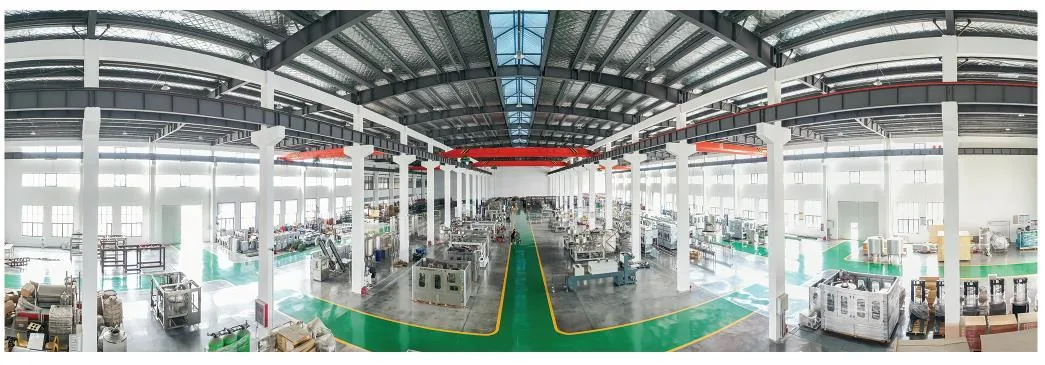
Real manufacturing reference from the Allot Tech Beverage Bottling Catalog 2026. Final equipment and layout remain project-specific.
01
Identify attachment and growth opportunities across the product path
Review drawings and inspect the installed system in normal production, idle, sanitation and maintenance states. Biofilm risk is not limited to obvious dead legs. Rough or scaled surfaces, gaskets, sample valves, filter housings, low-flow instruments and filler components can create protected microenvironments even in a nominally circulating loop.
Map hydraulic weakness
Identify branches with low or intermittent flow, oversized headers, standby trains, bypasses, high points, low points and lines isolated by production scheduling. Use measured or modeled evidence. A pump-running signal does not prove adequate exchange at every endpoint.
Inspect hygienic geometry
Review drainability, internal finish, weld condition, gasket intrusion, threaded or improvised connections, instrument pockets, spray coverage and accessibility. Record temporary hoses and repair fittings; they often outlive their intended short-term use.
Trace nutrient and contaminant entry
Assess raw or treated-water breakthrough, mineral additions, air, vent filters, lubricants, cleaning residues, packaging dust and maintenance activity. Very low nutrient does not mean zero growth potential. Link findings to source and sanitation controls.
Include the filler ecosystem
Map bowl, valves, vents, nozzles, centering parts, splash, external foam or lubricant, drains and environmental exposure. Determine which surfaces contact product, which can transfer indirectly and how the loop-filler interface is cleaned or disinfected.
02
Design circulation, treatment and sanitation as one control strategy
Continuous recirculation can reduce stagnation, but it must reach all qualified branches and remain compatible with treatment and product. Residual disinfectant, periodic physical or chemical sanitation and protective filtration each have limits. Define how the combined barriers control attachment without damaging materials or creating unacceptable product residues.
Maintain representative movement
Establish project-specific flow and turnover evidence through the whole loop, including endpoints and low-demand periods. Control valve positions and tank levels. Avoid publishing one universal velocity as a biofilm guarantee; geometry and surface condition matter.
Validate disinfectant distribution
Where a residual or periodic disinfectant is used, measure delivered condition at remote and return locations, effective exposure, decay and byproduct or material consequences. A generator setpoint does not prove action inside a shaded filler branch.
Integrate routine sanitation
Define the validated cycle, worst-case circuit, rinse and protected release. Ensure filler components and the product loop are not separated by an untreated interface. Plan around production length and idle states rather than sanitation only by convenient calendar.
Control temperature and storage
Evaluate tank residence, ambient heat gain, warm rooms and shutdown periods as part of the microbial growth opportunity. Use evidence-based alarm or operating rules. Cooling or lower temperature may help but does not repair a stagnant or rough circuit.
Control zone
Preventive evidence
Leading signal
Escalation decision
Tank and recirculation loop
Turnover, circulation and hygienic condition
Location-based microbial and process trend
Investigate hydraulics, surface and sanitation
Branches and use points
Exchange or flush state and cleanable geometry
Recurring point-specific elevation
Hold use point; inspect and restore
Filler and product interface
Validated sanitation plus protected operation
Nozzle/bowl trend or environmental linkage
Define product boundary and intensify investigation
Post-maintenance state
Controlled intervention and hygienic release
Unexpected result after work
Stop, assess restoration and resample
03
Detect trends early with a purposeful sampling design
Biofilm is spatial and episodic, so one negative finished-product result cannot clear the whole system. Choose sample points that represent source, post-treatment, tank, supply, remote branch, return and filler, with timing tied to startup, run length, sanitation and idle state. Preserve methods, sample technique and environmental context.
Use location as information
Keep results tied to a stable point identity and flow state. Compare upstream and downstream pairs to localize emerging growth. Rotating unlabeled taps may increase sample count while destroying the ability to interpret a pattern.
Control sample technique
Design hygienic sample valves, define flushing or first-draw state, sanitize externally where appropriate and train samplers. Record unusual operation. False contamination and overly aggressive flushing can respectively exaggerate or hide a local problem.
Combine complementary evidence
Use microbial methods suitable for the product and regulatory context, together with process indicators, inspection, sanitation records and targeted surface assessment where justified. No single method detects every biofilm state or organism.
Trend before specification failure
Review repeated low-level changes, location clustering, time after sanitation, organism pattern and coincident flow or maintenance events. Set investigation signals from the site's baseline and risk; do not invent a universal action number.
04
Intervene without dispersing risk and verify durable recovery
When trends indicate possible establishment, control affected water and investigate before applying a stronger chemical blindly. Increased flow or sanitation can release attached material downstream. Define isolation, product hold, sampling and safe waste routing, then verify that the corrective action addresses the harborage and not only the test result.
Set the product boundary
Use last acceptable system state, tank and loop residence, filler timing and lot coding to identify potentially affected product. Hold and evaluate under the approved food-safety process. Negative adjacent samples should not automatically shrink a poorly understood boundary.
Investigate the mechanism
Review organisms or pattern, hydraulics, temperature, nutrients, scale, surface defects, gaskets, filter state, sanitation delivery, open interventions and sample validity. Target inspection or disassembly where evidence points rather than dismantling the whole plant without a plan.
Restore safely
Remove or replace damaged or heavily colonized components where cleaning evidence is insufficient, execute a validated restoration cycle, control flush waste and protect the system from reentry. Confirm material compatibility for any intensified treatment.
Verify sustained effectiveness
Use a risk-based follow-up sequence across affected and downstream points, normal production length and relevant idle states. Track corrective actions and update design, sanitation or maintenance controls. A single negative resample is weak closure for an established trend.
R
References and verification boundary
These sources support the risk-control method on this page. They do not set project-specific legal limits, test frequencies, engineering values or approvals; verify the current edition and local applicability before a decision.
No. It can reduce stagnation but does not eliminate nutrients, rough surfaces, weak branches, temperature effects or contamination. Verify the complete design and operating strategy.
Can finished-product testing prove the loop is clean?
No. It samples limited bottles at one time. Use location-based water and process trends, hygienic inspection, sanitation evidence and targeted investigation together.
Should disinfectant dose be increased after an elevated result?
Not automatically. Control product, verify the result, investigate location and mechanism, and confirm material and byproduct implications before changing a validated process.
Is biofilm the same as a positive planktonic water sample?
No. A water result may indicate shedding or transient contamination, while attached communities can persist without constant detection. Interpret repeated spatial and temporal evidence.
What inputs support a biofilm-control review?
Provide current P&IDs, flow and turnover data, treatment and sanitation validation, sample-point map and trends, organism information, temperatures, maintenance history, surface condition and recent changes.
Move this project question forward
Need to resolve How to Prevent Biofilm in the Product-Water Loop and Filler for your water bottling plant?
Biofilm is spatial and episodic, so one negative finished-product result cannot clear the whole system. Choose sample points that represent source, post-treatment, tank, supply, remote branch, return and filler, with timing tied to startup, run length, sanitation and idle state. Preserve methods, sample technique and environmental context.
Not sure which data matters? Send what you have and state the decision you need to make.
2. Attach the decision inputs
Map hydraulic weakness
Maintain representative movement
Use location as information
Set the product boundary
Send target capacity and SKUs, source-water report, site utility schedule, building layout and required project milestones.
3. Confirm the next planning step
The project desk can identify missing inputs and a practical next step. Final engineering, configuration, compliance and commercial terms remain project-specific.