Water Bottling Plant Electrical Distribution Planning
A bottling line cannot be connected safely from one headline power number. Treatment pumps, compressors, blowers, chillers, heaters, fillers, conveyors, packers, laboratories and building services create different starting currents, duty patterns and criticality. Electrical planning should convert the confirmed equipment list into a load schedule, distribution architecture, installation boundary and test plan that qualified local professionals can complete against applicable requirements.
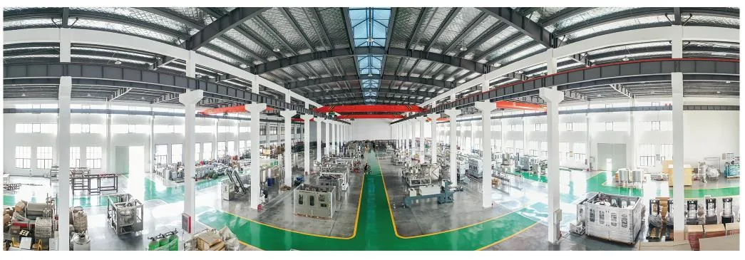
Real manufacturing reference from the Allot Tech Beverage Bottling Catalog 2026. Final equipment and layout remain project-specific.
01
Create a controlled electrical load schedule
Use equipment documents and operating scenarios instead of adding catalog nameplate values without context.
Identify every connected load
List process equipment, packaging machines, utility generation, HVAC, laboratory, warehouse, lighting, offices, fire and safety systems. Record voltage, phase, frequency, rated and starting current, motor method, duty, power factor, heat release and supplier connection point.
Separate demand from installed capacity
Show which loads run continuously, intermittently, during sanitation, during startup or only as standby. Define realistic production and cleaning scenarios so transformer and generator discussions use coincident demand rather than an unsupported total.
Classify operational criticality
Identify loads needed to protect product, finish a controlled stop, preserve controls or restart after an outage. This classification informs backup power, uninterruptible supplies, selective isolation and the sequence for restoring production.
02
Define the distribution and responsibility boundary
Every panel, cable and final connection needs an owner and an approved design basis.
Distribution layer
Planning decision
Interface evidence
Responsible party to name
Incoming supply
Available capacity, voltage quality, metering and utility point
Utility data and site survey
Utility, buyer or local electrical party
Main distribution
Transformer, main board, protection, segregation and reserve
Single-line diagram and load schedule
Qualified local designer and installer
Machine distribution
Panel locations, feeders, isolation and cable routes
Equipment electrical drawings and connection list
Supplier, integrator and local installer
Control power
UPS, networks, backups and clean shutdown needs
Control narrative and recovery procedure
Controls supplier and plant technical team
03
Coordinate cables, environment and maintainability
A correct calculation still fails if the installed route conflicts with water, heat, traffic or maintenance.
Route and segregation
Coordinate trays, trenches, conduits, penetrations and drops with hygienic zones, washdown, drains, hot surfaces, compressed-air piping, forklifts and future access. Separate power, controls and sensitive instrumentation where the design requires it.
Protection and earthing
Qualified parties should determine fault levels, protective-device coordination, cable sizing, earthing, bonding, lightning and surge protection using actual local supply and installation conditions. Machine documentation supplies inputs but does not replace the local design.
Panels and working space
Reserve dry, ventilated, accessible locations with required clearances, identification, isolation and safe maintenance routes. Document spare ways and physical reserve only when the associated expansion scenario is defined.
04
Test the electrical system as part of plant startup
Acceptance evidence should connect installation checks to machine and line operation.
Pre-energization review
Verify drawings, labels, cable and termination records, protective settings, earthing results, enclosure condition, isolators, emergency circuits and unresolved work before controlled energization.
Functional and load testing
Check phase sequence, voltage, current, protection, interlocks, emergency stops, restart logic and representative operating loads. Observe startup of large motors and simultaneous utility demand under agreed conditions.
Handover and change control
Deliver approved drawings, settings, panel schedules, backups, test reports, spare-parts data and isolation procedures. Require the load schedule and single-line diagram to be updated when equipment or operating modes change.
Buyer questions
Questions to settle before the next project gate
How much electrical power does a water bottling plant require?
It depends on treatment, bottle blowing, air compression, cooling, heating, packaging, building services and which loads operate together. Build the answer from a project load schedule.
Can a machine supplier design the complete site electrical system?
The supplier can provide machine loads and interface drawings. Qualified local professionals should complete and approve the site distribution design under applicable requirements.
Should every machine be connected to backup power?
Not automatically. Classify safety, product, control and recovery needs, then define which loads require UPS, generator supply or controlled shutdown.
What should be sent for electrical planning?
Send the equipment list, load data, utility supply information, measured site layout, operating scenarios, backup objectives, environmental conditions and local electrical requirements.
Move this project question forward
Need to resolve Water Bottling Plant Electrical Distribution Planning for your water bottling plant?
A correct calculation still fails if the installed route conflicts with water, heat, traffic or maintenance.
Not sure which data matters? Send what you have and state the decision you need to make.
2. Attach the decision inputs
Identify every connected load
Route and segregation
Pre-energization review
Separate demand from installed capacity
Send target capacity and SKUs, source-water report, site utility schedule, building layout and required project milestones.
3. Confirm the next planning step
The project desk can identify missing inputs and a practical next step. Final engineering, configuration, compliance and commercial terms remain project-specific.